
shopping_bag Cart Items (0)
₹0.00
remove_shopping_cart
Your procurement cart is empty
Browse Spares Catalog
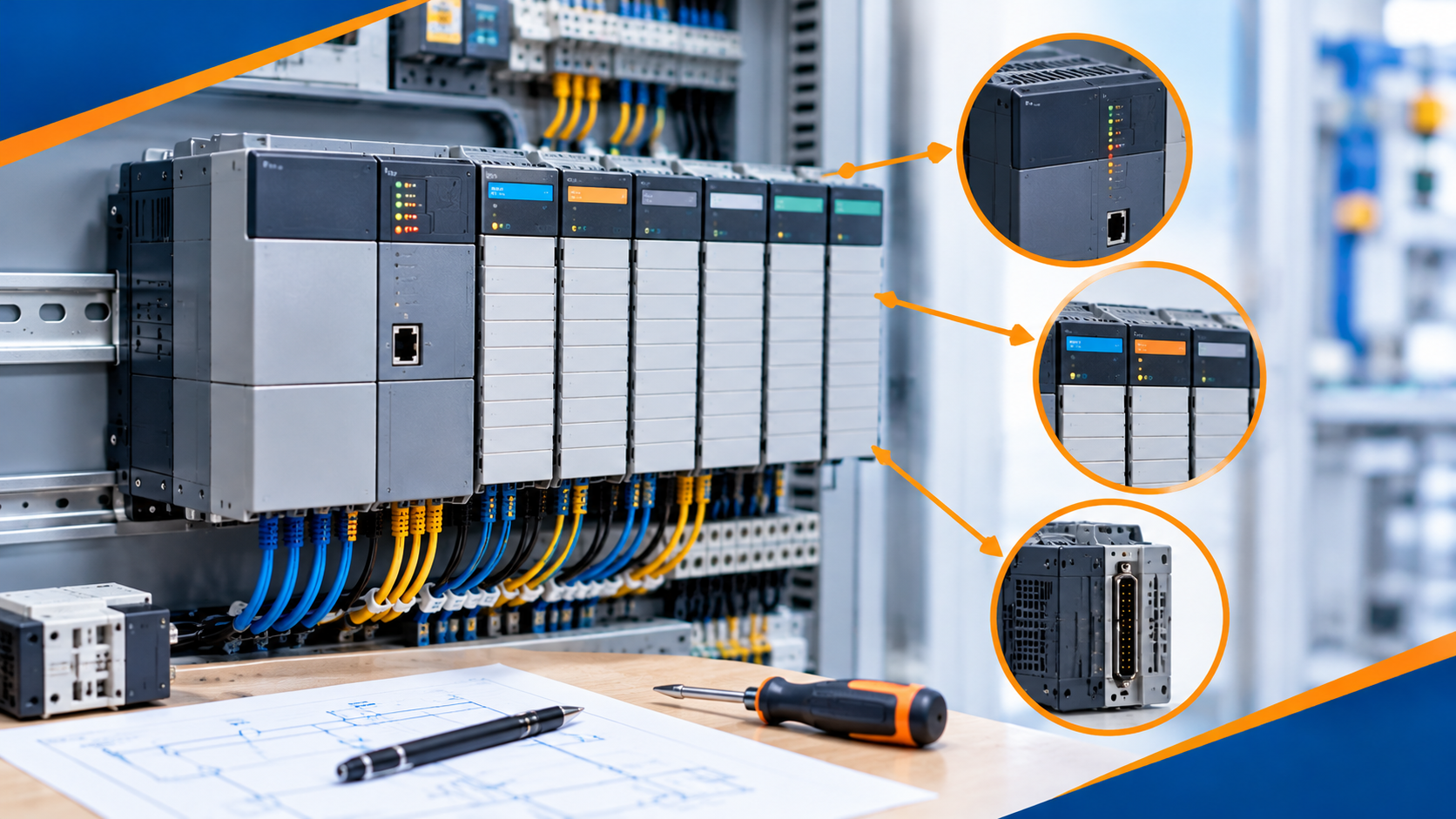
Identifying industrial automation hardware correctly is one of the most important skills on the factory floor. A Programmable Logic Controller (PLC) is a rugged industrial computer that runs automated machinery. In any control cabinet, PLC modules process inputs, run control logic, and drive physical outputs like motors and valves.
When a module fails during a machine breakdown, picking the wrong replacement part can cause project delays, blown fuses, or controller faults. In this practical guide on How to Identify Allen-Bradley PLC Modules, you will learn how to decode catalog numbers, verify series hardware revisions, check software properties, and inspect status LEDs with complete confidence.
Every piece of Allen-Bradley hardware manufactured by Rockwell Automation carries a specific model designation. Think of a PLC module's catalog number like the VIN (Vehicle Identification Number) on a car. A single letter difference in the part number can mean the difference between a 24V DC input module and a 120V AC input module.
Knowing how to identify Allen-Bradley PLC modules helps control technicians:
Order Correct Replacements: Prevents ordering incompatible voltage or channel configurations.
Troubleshoot Mismatches: Resolves electronic keying faults inside programming software.
Verify Spare Parts Inventory: Ensures backup inventory matches active cabinet hardware.
Plan Platform Upgrades: Identifies end-of-life legacy components before they cause unplanned downtime.

Allen-Bradley uses a standardized numbering system across its hardware lines. Every catalog number contains a bulletin number, product family code, and specific feature modifiers.
The first three or four digits indicate the hardware bulletin series.
1746: SLC 500 system modules.
1747: SLC 500 processors and specialty cards.
1756: ControlLogix chassis, CPUs, and I/O modules.
1769: CompactLogix and Compact I/O expansion cards.
5069: Compact 5000 I/O modules for modern CompactLogix controllers.
Following the bulletin number, letters define the module type:
I: Digital Input module (e.g., 1756-IB16 where I = Input, B = 24V DC, 16 = 16 channels).
O: Digital Output module (e.g., 1746-OW16 where O = Output, W = Relay contacts, 16 = 16 points).
N: Analog Module (e.g., 1746-NI4 where N = Analog, I = Input, 4 = 4 channels).
L: Processor / Controller (e.g., 1756-L73 or 5069-L320ERM).
The letters right after the module type indicate signal levels:
A: 120V AC discrete signal.
B: 24V DC sinking or sourcing discrete signal.
W: Relay contact outputs (isolated dry contacts).
VI / VO: Analog Voltage/Current modules.
| Sample Part Number | Bulletin / System | Module Function | Key Specification |
1756-IB16D |
1756 (ControlLogix) | Digital Input | 24V DC Diagnostic Input, 16 Points |
1746-OW16 |
1746 (SLC 500) | Digital Output | Mechanical Relay Output, 16 Points |
1769-IF4 |
1769 (CompactLogix) | Analog Input | 4-Channel Analog Current/Voltage |
5069-OB16 |
5069 (Compact 5000) | Digital Output | 24V DC High-Speed Output, 16 Points |
Every physical module features a side or door label printed at the factory. Reading this label correctly reveals essential hardware details.
Front Door Panel: Open the hinged plastic terminal cover to read the primary model number and wiring diagram.
Side Housing Sticker: Pull the module partially out of the rack to inspect the main white rating label on the side plastic casing.
Series Letter (e.g., Series A, Series B): Represents physical hardware changes or board redesigns made during manufacturing.
Firmware Revision (e.g., Rev 3.002): Indicates the internal operating code running on the microprocessor.
Safety Tip: Always check the Series Letter when replacing older analog modules. Terminal block layout or backplane power draw can vary between Series A and Series B cards.
If the physical label on a module is damaged, faded, or covered in dust, you can identify the device using software tools across the network.
Open RSLinx Classic and launch the RSWho network browser.
Navigate through your network tree (EtherNet/IP or serial) to locate the target chassis.
Expand the rack backplane to view all installed slot numbers.
Right-click the target module and select Device Properties.
Read the vendor name, catalog number, major/minor firmware revision, and serial number.
Open your online project inside Studio 5000 Logix Designer.
Go to the Controller Organizer window on the left side.
Expand the I/O Configuration folder to view the configured slot tree.
Double-click any module and select the Module Info tab.
The software will display the connected module's exact identity, installed firmware revision, and electronic keying status.
Imagine a 24V DC input module fails on a packaging line, causing an emergency stop circuit fault.
Physical Inspection: You open the cabinet and check the module door label. It reads 1756-IB16 Series A.
Stock Verification: You check the spare parts room and find a box labeled 1756-IA16.
Decoding the Part: You spot the letter A in 1756-IA16. This means it is a 120V AC module, not a 24V DC module (IB16)!
Correct Action: You avoid installing the wrong card—which would have damaged field sensors—and retrieve a true 1756-IB16 matching card.
Avoid these frequent mistakes when identifying hardware in active industrial environments:
Confusing the Terminal Block Part Number: The removable terminal block (RTB) has its own part number (e.g., 1756-TBCH). Do not mistake the terminal connector part number for the main I/O module number!
Ignoring Electronic Keying Settings: Studio 5000 uses Electronic Keying to verify module identity. If "Exact Match" is selected in software, replacing a Series A card with a Series B card will cause an I/O configuration fault.
Relying Only on LED Indicators: Status LEDs show health (OK, RUN, FAULT), but they do not confirm model numbers. Always verify catalog numbers via side labels or software properties.
Learning How to Identify Allen-Bradley PLC Modules ensures fast troubleshooting and reliable system maintenance. By understanding bulletin numbering formats, checking side rating labels, and using RSLinx or Studio 5000 diagnostic tools, engineers can verify any module in minutes. Accurate identification keeps spare parts inventory organized and prevents costly wiring mistakes during machine breakdowns.
Do you have questions about cross-referencing an older Allen-Bradley module or clearing an I/O keying fault? Leave a comment below or contact our technical support team at plchub.in today!
The catalog number is printed on the front hinged door label and on the primary specification sticker located on the side of the module housing. You can also view it in software via RSLinx Classic or Studio 5000.
The Series letter (e.g., Series A or B) indicates physical hardware or circuit board manufacturing revisions. The Revision number (e.g., Rev 2.001 or 3.002) refers to the internal software/firmware version running on the device.
Connect your PC to the PLC network using RSLinx Classic. Open the RSWho tool, locate the chassis backplane, right-click the target module slot, and select Device Properties to view the hardware catalog number.
The prefix "1756" is the Allen-Bradley bulletin number that designates the ControlLogix family of chassis, processors, communication cards, and I/O modules.
Keep the site working: signing in, your cart and checkout, security checks and remembering these privacy choices. These cannot be switched off.
Remember products you viewed and searches you made so we can show "recently viewed" items and relevant suggestions, linked to your account when you sign in.
Help us understand how visitors use the site (pages visited, time spent, country) so we can improve it. Without this we only count anonymous daily totals.
Allow advertising, chat and notification partners to set cookies so we can measure campaigns, show relevant offers and offer live chat and push notifications.