
shopping_bag Cart Items (0)
₹0.00
remove_shopping_cart
Your procurement cart is empty
Browse Spares Catalog
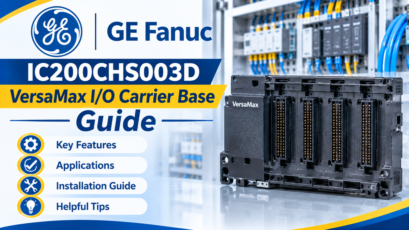
Industrial control panels require sturdy physical foundations to link field wiring with electronic controller modules. A Programmable Logic Controller (PLC) relies on modular base carriers to hold input and output cards securely while routing electrical signals.
The GE Fanuc IC200CHS003D VersaMax Barrier Style I/O Carrier Base Module Terminal Block is a reliable mounting base engineered by GE Fanuc (now Emerson/Machining automation). Built for VersaMax modular control systems, it provides secure barrier-style screw terminal connections. In this guide, you will learn how this carrier base operates, its core technical specifications, proper installation guidelines, and troubleshooting tips.
The GE Fanuc IC200CHS003D VersaMax Barrier Style I/O Carrier Base Module Terminal Block is a modular base plate that snaps onto a standard DIN rail inside an electrical enclosure. Think of it like a electrical outlet socket strip in your home wall. The socket stays permanently wired to your appliances, allowing you to plug or unplug electronic devices safely without tearing out the building wiring.
In factory automation, field sensors and actuators wire directly into the screw terminals on the IC200CHS003D carrier base. The electronic I/O module then plugs directly into the top of the carrier, making hardware replacement fast and effortless.
| Parameter | Technical Specification / Rating |
| Catalog Number | IC200CHS003D |
| Product Family | GE Fanuc / Emerson VersaMax I/O System |
| Terminal Style | Barrier Style Screw Terminals |
| Mounting Type | 35mm DIN Rail mounting |
| Module Compatibility | Standard VersaMax discrete and analog I/O modules |
| Enclosure Protection | IP20 industrial finger-safe housing |
GE Fanuc engineered the VersaMax carrier series to simplify panel wiring and withstand harsh plant environments.
The "003" designation indicates a barrier style terminal block. Raised plastic dividers (barriers) separate each individual screw terminal. This design prevents stray wire strands from shorting against adjacent terminals, ensuring safe high-density wiring connections.
The base carrier mounts securely onto standard 35mm DIN rails. Interlocking side latches allow multiple carrier bases to snap together side-by-side, creating a seamless backplane bus that distributes power and communication signals automatically.
VersaMax carriers support module replacement without turning off main panel power. Technicians can snap a failed I/O module off the IC200CHS003D base and snap a new one in its place without disturbing field wiring.
Consider a municipal water treatment facility upgrading a chemical dosing control panel.
The Challenge: The control panel requires additional 24V DC digital input points to monitor new flow meters and tank level float switches.
The Solution: Engineers snap several GE Fanuc IC200CHS003D VersaMax Barrier Style I/O Carrier Base Module Terminal Block units onto the existing DIN rail alongside current bases.
Execution: Electricians wire field sensor cables directly into the barrier screw terminals. Digital input modules plug into the top of each base carrier.
Result: Clean, organized field wiring with easy modular expansion capabilities that minimize panel footprint and installation time.
Avoid these frequent operational errors when installing or maintaining VersaMax I/O bases:
Verify Terminal Screw Torque: Always tighten barrier screw terminals to recommended torque specs. Loose terminal screws cause high electrical resistance, intermittent sensor signals, and localized heat buildup.
Check Interlocking Bus Connectors: When snapping multiple carrier bases together, ensure the side communication and power pins align correctly. Misaligned backplane pins will cause module configuration faults inside the PLC software.
Label Field Wires Clearly: Because barrier terminals pack many connections into a small space, always use printed wire markers corresponding to your electrical schematics to speed up future troubleshooting.
The GE Fanuc IC200CHS003D VersaMax Barrier Style I/O Carrier Base Module Terminal Block is an essential hardware component for reliable industrial control panel design. By understanding its barrier terminal safety features, DIN-rail mounting architecture, and modular replacement benefits, control engineers can maintain factory systems with total confidence. Proper installation ensures secure electrical connections and long-term uptime.
Do you have questions about configuring VersaMax I/O systems or sourcing GE Fanuc automation parts? Leave a comment below or contact our technical support team at plchub.in today!
Barrier style refers to the raised plastic partitions separating individual screw terminals, which prevent stray wire strands from causing accidental electrical shorts between terminals.
Yes. The VersaMax carrier base remains permanently wired to field devices. You can plug or unplug the electronic I/O module from the top of the base without touching the screw terminals.
VersaMax I/O modules and carrier bases work with GE Fanuc Micro, Nano, and modular CPU controllers, as well as remote I/O network interface units.
Adjacent carrier bases connect via integrated sliding backplane connectors on their sides, automatically passing power and data signals down the rail.
Keep the site working: signing in, your cart and checkout, security checks and remembering these privacy choices. These cannot be switched off.
Remember products you viewed and searches you made so we can show "recently viewed" items and relevant suggestions, linked to your account when you sign in.
Help us understand how visitors use the site (pages visited, time spent, country) so we can improve it. Without this we only count anonymous daily totals.
Allow advertising, chat and notification partners to set cookies so we can measure campaigns, show relevant offers and offer live chat and push notifications.