
shopping_bag Cart Items (0)
₹0.00
remove_shopping_cart
Your procurement cart is empty
Browse Spares Catalog
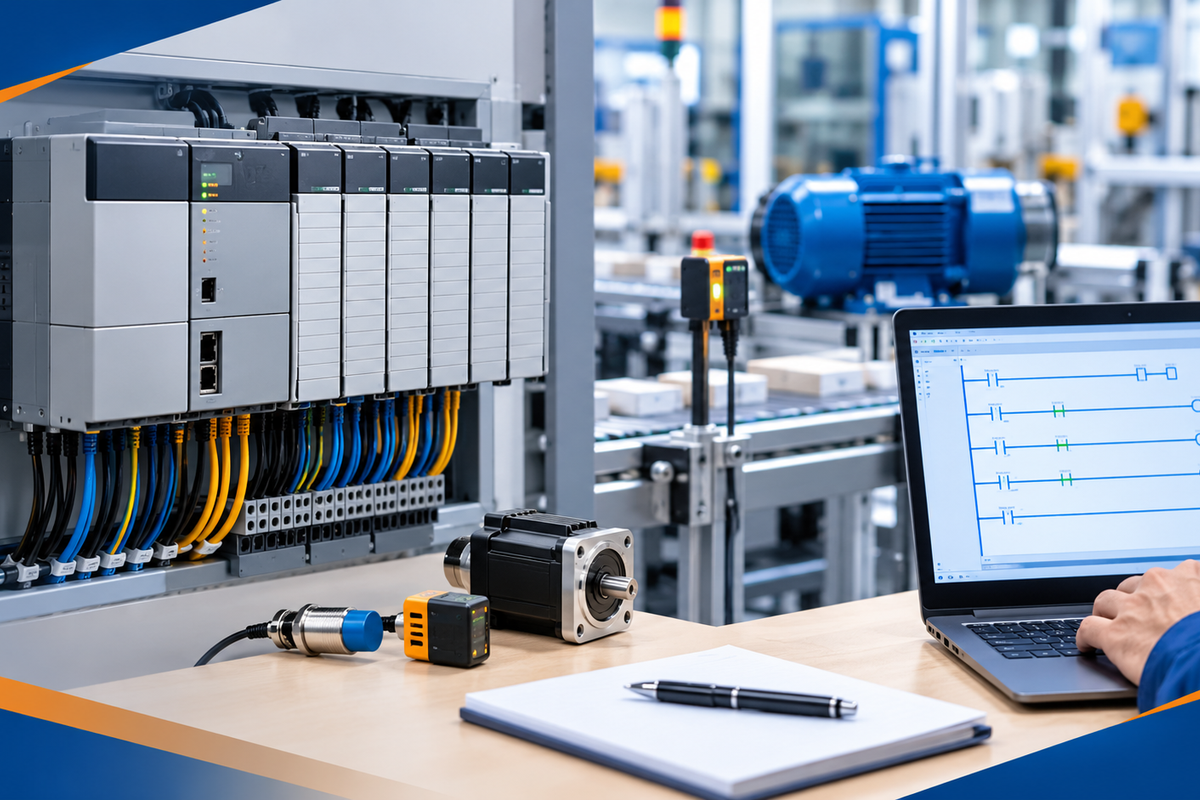
The Allen-Bradley SLC 500 platform is one of the most successful controller series in industrial history. Introduced by Rockwell Automation in 1991, this modular system automated millions of factory machines globally. A Programmable Logic Controller, or PLC, is a rugged industrial computer that reads field inputs, executes a program, and controls machinery output devices.
Whether you are maintaining operational legacy machinery or planning a system upgrade, this Allen-Bradley SLC 500: Complete Guide provides essential technical knowledge. You will learn how the hardware operates, how data addressing works, how to clear system faults, and how to plan migration paths effectively.
The Allen-Bradley SLC 500 (Small Logic Controller) is a modular, rack-based control system built for small-to-medium factory automation tasks. Think of a PLC rack as the control center of an automated assembly line. Just as a driver observes road signs and operates pedals to steer a car, the PLC collects sensor data and controls motors or valves to run a machine.
Rockwell Automation engineered the 1746 SLC family to deliver high reliability in harsh plant environments. It bridges the operational gap between compact fixed controllers and larger ControlLogix chassis architectures.
Modular Backplane Architecture: Power supplies, processors, and field I/O modules install directly into standard chassis slots.
Industrial Hardening: Designed to withstand heavy mechanical vibration, high ambient temperatures, and electrical noise.
RSLogix 500 Platform: Programmed using standard ladder logic, which mimics traditional electrical relay control schematics.
Long Operational Lifespan: Millions of installed modules remain active in continuous factory production today.


An operational SLC 500 system consists of five primary hardware components. Each part handles a distinct operational task inside the control cabinet.
The chassis is the structural metal frame that houses system modules. It contains a printed circuit backplane that delivers system power and routes data signals between modules. Racks come in 4-slot, 7-slot, 10-slot, and 13-slot options. Slot 0 is reserved for the system processor module.
Mounting on the left end of the chassis, the power supply converts external AC line voltage (120V/240V) or DC control voltage (24V) into regulated internal DC power. This powers the internal circuitry of all connected rack modules across the backplane.
The CPU module occupies Slot 0 and runs the user control program. Rockwell produced several processor iterations:
SLC 5/01 & 5/02: Base processors featuring small memory allocations and basic DH-485 serial communication.
SLC 5/03: Includes a dedicated RS-232 serial port, higher execution speed, and online programming support.
SLC 5/04: Features Data Highway Plus (DH+) networking for high-speed plantwide communications.
SLC 5/05: Equips a 10/100 Mbps Ethernet port for direct integration with standard modern industrial networks.
1746 I/O modules form the physical connection between internal control logic and plant floor field devices.
Digital Input Modules: Receive discrete signals from pushbuttons, limit switches, and proximity sensors.
Digital Output Modules: Switch electrical current to actuate motor starters, solenoid valves, and indicator stack lights.
Analog Modules: Process variable voltage or current signals (4-20mA, 0-10V) from temperature transmitters and pressure transducers.
SLC 500 processors support multiple industrial communication protocols. Depending on the CPU model installed, connectivity options include Ethernet/IP, DH+, DH-485, DeviceNet, and RS-232 serial links.
To monitor ladder logic programs or troubleshoot forced bits, control engineers must understand how memory is structured. The SLC 500 organizes internal processor data into categorized data files.
| Data File Type | Identifier | Function / Hardware Description |
| Output File | O0: |
Stores physical output channel terminal states. |
| Input File | I1: |
Stores physical input channel terminal states. |
| Status File | S2: |
Tracks system processor diagnostics, scan time, and error codes. |
| Bit File | B3: |
Stores internal binary flags, logic latches, and interlocks. |
| Timer File | T4: |
Holds timing structure data (TON, TOF, RTO instructions). |
| Counter File | C5: |
Tracks pulse count accumulators and preset values (CTU, CTD). |
| Control File | R6: |
Manages bit shift registers and stack pointers. |
| Integer File | N7: |
Stores 16-bit signed numerical values (-32,768 to +32,767). |
| Float File | F8: |
Stores 32-bit floating-point decimal numbers. |
Consider the field input address I:2/5:
I designates the Input Data File.
2 identifies the physical chassis slot number (Slot 2).
/5 references bit or terminal point 5 on that specific module card.
Consider a high-speed package sorting conveyor controlled by an Allen-Bradley SLC 5/05 processor.
Detection Input: A optical photo-eye detects a package on the belt and energizes input terminal I:1/2.
Logic Evaluation: The CPU evaluates the ladder program inside RSLogix 500. If internal timer T4:1.DN (Done Bit) is true, the program activates internal control bit B3:0/12.
Pneumatic Output: Logic turns ON physical output point O:3/4.
Physical Actuation: Output O:3/4 sends 24V DC to a solenoid valve, extending a pneumatic pusher to divert the box into a side chute.
This control loop executes continuously inside the CPU during every processor scan cycle.
Maintaining legacy Allen-Bradley SLC 500 hardware requires structured diagnostic techniques.
SLC 500 processors rely on an internal lithium battery to maintain volatile memory when main cabinet power is disconnected.
If the CPU BATT LED illuminates solid red, replace the battery immediately while power is applied to the rack.
Always archive a fresh .RSS project file backup on a local engineering workstation.
When the CPU enters a faulted state, the FLT LED flashes red.
Connect an engineering PC using RSLogix 500.
Go online with the processor and access the Processor Status File (S2) window.
Check word S:6 to read the specific major fault code.
Common errors include index overflow, division by zero, or bad expansion cable connections.
Rockwell Automation has transitioned the SLC 500 series to silver series and end-of-life status. When planning platform modernization:
Retain field wiring by using 1746-to-5069 migration wiring harness kits.
Convert legacy ladder programs automatically using Rockwell's project migration tools into Studio 5000 Logix Designer.
Replace older SLC CPUs with modern CompactLogix 5380 controllers for higher memory capacities and faster gigabit Ethernet speeds.
The Allen-Bradley SLC 500 remains an essential reference platform in modern control engineering history. Understanding its 1746 chassis architecture, data addressing structures, and fault diagnostics ensures legacy systems run safely. As hardware components reach end-of-life, combining sound troubleshooting with proactive migration strategies keeps manufacturing facilities operating without unexpected downtime.
Have questions about diagnosing an SLC 500 backplane fault or selecting CompactLogix migration options? Contact our automation experts at plchub.in or join the discussion in the comments section below!
The primary programming software for the SLC 500 family is RSLogix 500. You can also configure selected compact systems using MicroLogix-compatible software tools.
The main difference is the primary communication port. The SLC 5/04 uses a blue-hose Data Highway Plus (DH+) network port, while the SLC 5/05 includes an RJ45 10/100 Mbps Ethernet port.
No. The SLC 500 chassis backplane does not support Removal and Insertion Under Power (RIUP). Always turn off main supply power before pulling or inserting any chassis module to avoid hardware damage.
Go online with the controller using RSLogix 500, read the fault code in File S2, resolve the underlying hardware or code condition, clear the fault error bit, and switch the key from PROG to RUN mode.
Keep the site working: signing in, your cart and checkout, security checks and remembering these privacy choices. These cannot be switched off.
Remember products you viewed and searches you made so we can show "recently viewed" items and relevant suggestions, linked to your account when you sign in.
Help us understand how visitors use the site (pages visited, time spent, country) so we can improve it. Without this we only count anonymous daily totals.
Allow advertising, chat and notification partners to set cookies so we can measure campaigns, show relevant offers and offer live chat and push notifications.